Zuko

Zuko is a quadruped robot dog inspired by such dogs like Spot Mini Mini and Baris Alp's Kangel.
Although Zuko is an incomplete project, I wanted to share him hopefully inspiring others to explore making their own robot dogs.
This is a video of the first full inverse kinematics test - a bit clunky, but a good start!
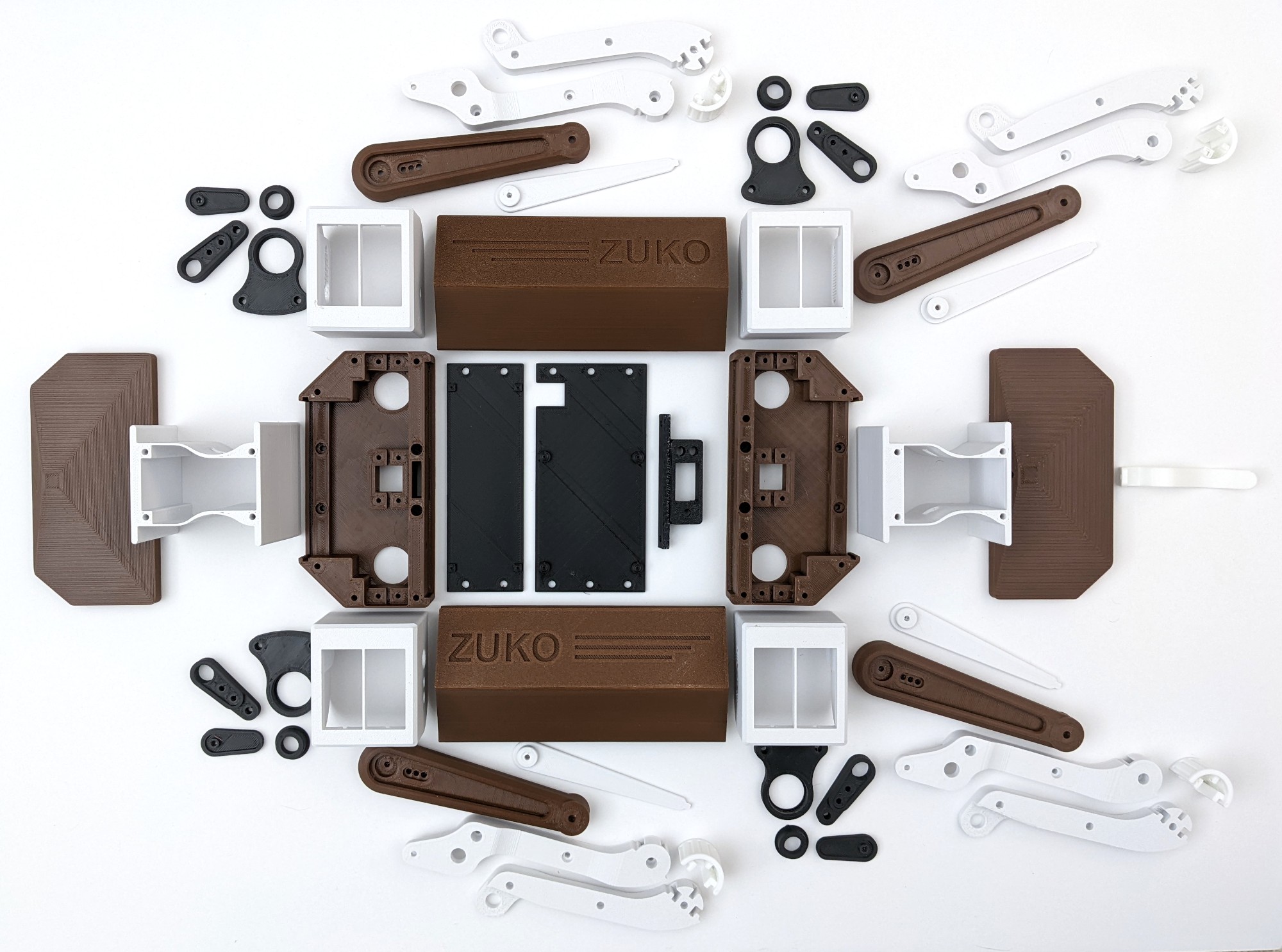
Every printed part was designed using Fushion 360 with the goal of minimizing frame size, part count, and keeping a sense of aesthetics all while keeping the parts simple to print. All the parts are printed in ABS but for future builds I will consider using PETG for easier printing and better dimensional stability.
Total assembled weight (frame, motors, electronics, and batteries) is about 2.2kg.
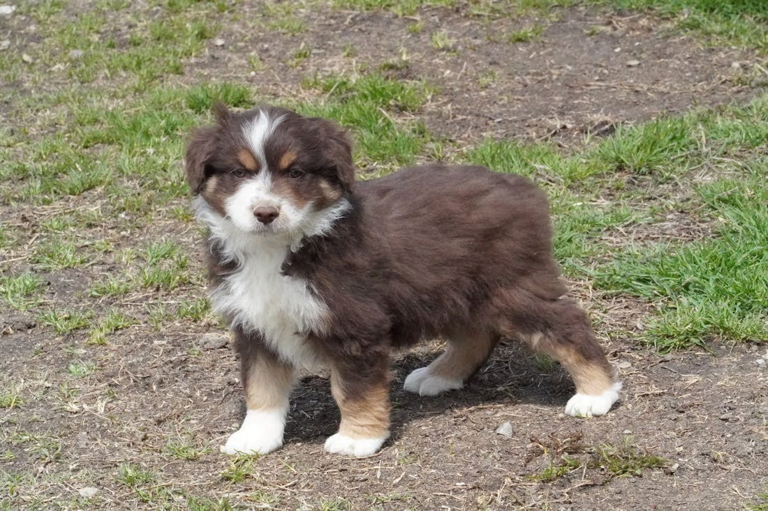
This is Zuko, a Australian shepherd. Over the Covid 19 pandemic my girlfriend wanted a puppy and found a beautiful black tri Australian Shepherd. While picking her up Zuko, a spunky brown tri, was also available and I thought this was my chance to also have my own puppy - I was summarily denied puppy ownership by my girlfriend. She made a strong case that Australian Shepherds need large amounts of attention and activity but I being a typical engineer tend to fall into projects with the rest of world going unnoticed. I reluctantly agreed and went with the best second option, building my own puppy!
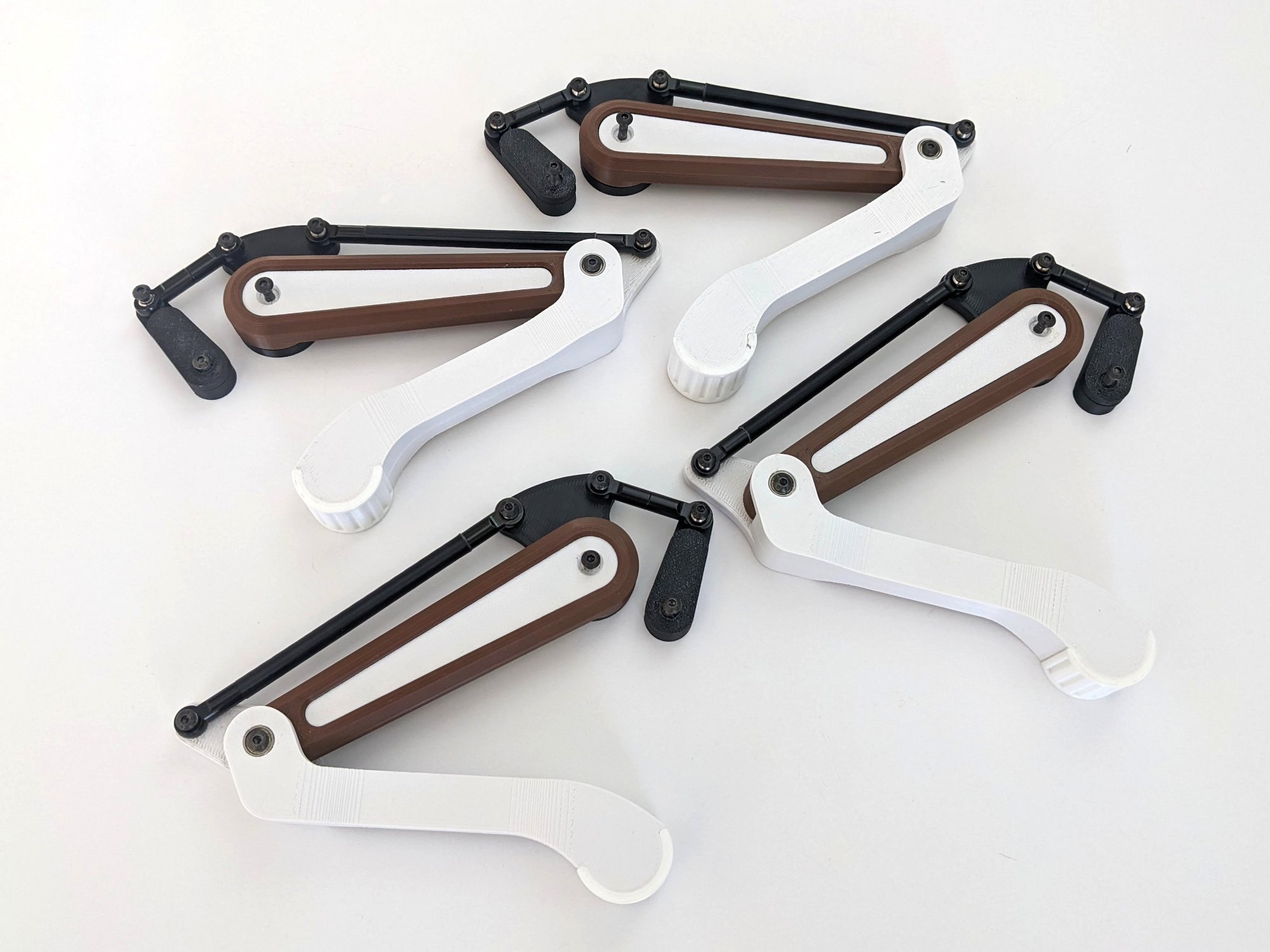
Here are the legs all assembled and ready to go. Since this picture I swapped out the TPU feet with black EVA foam for one less filament type and better grip.
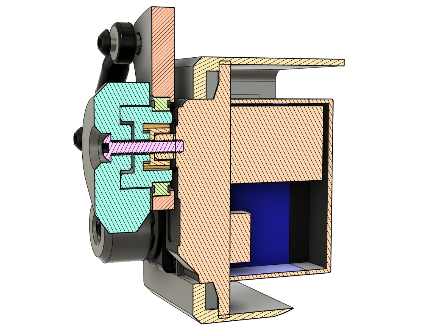
Leg motor cross section. The cross section tool in Fushion 360 as invaluable for testing against hardware collisions and ensuring enough material exists for structural rigidity.
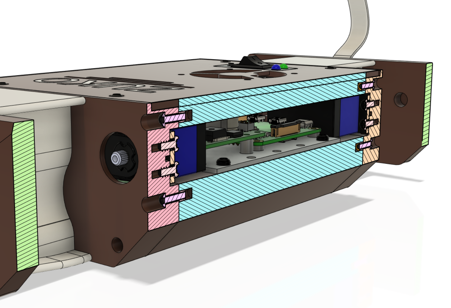
Body cross section.
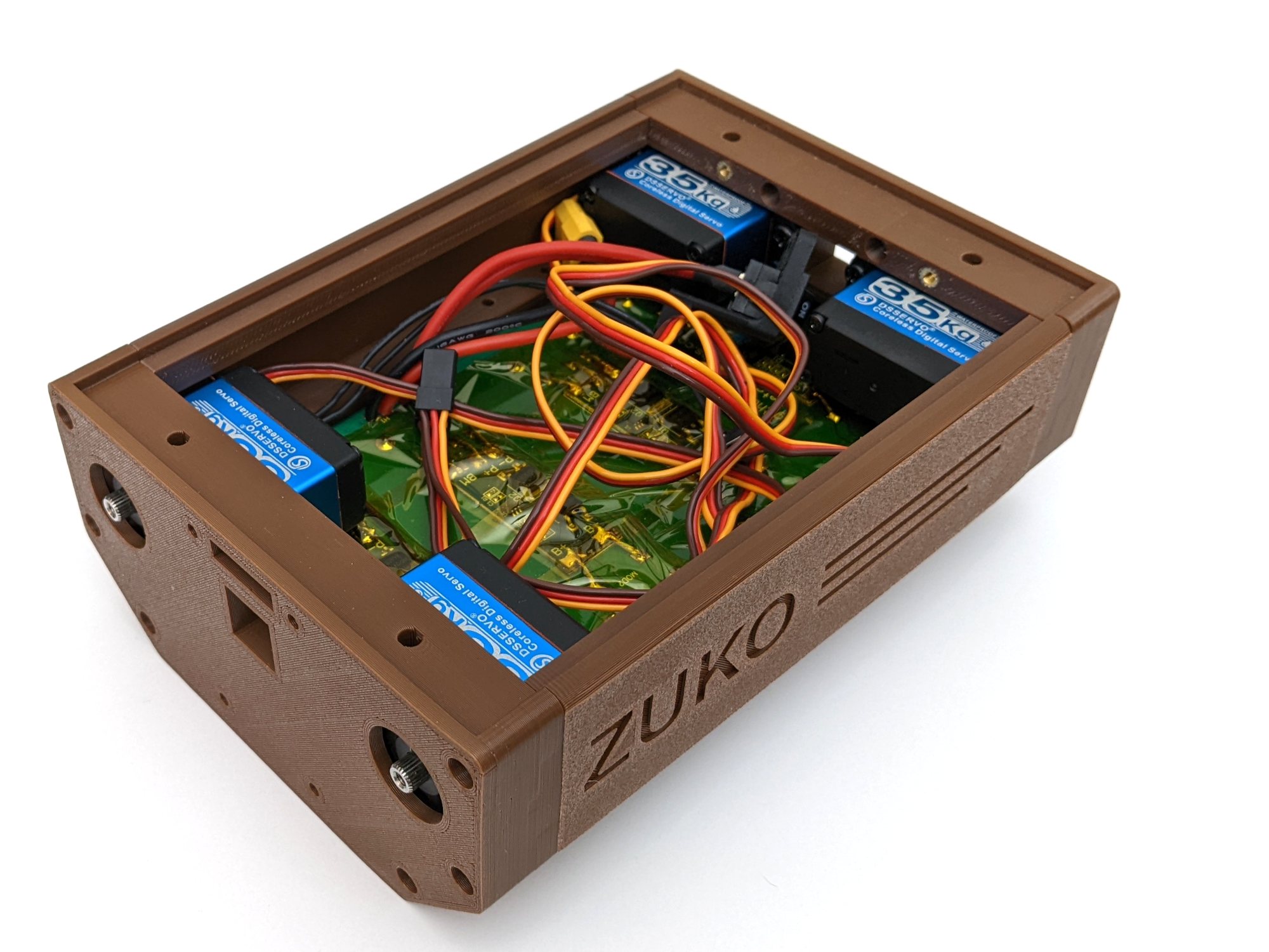
The center frame assembled and ready for the hip assemblies.
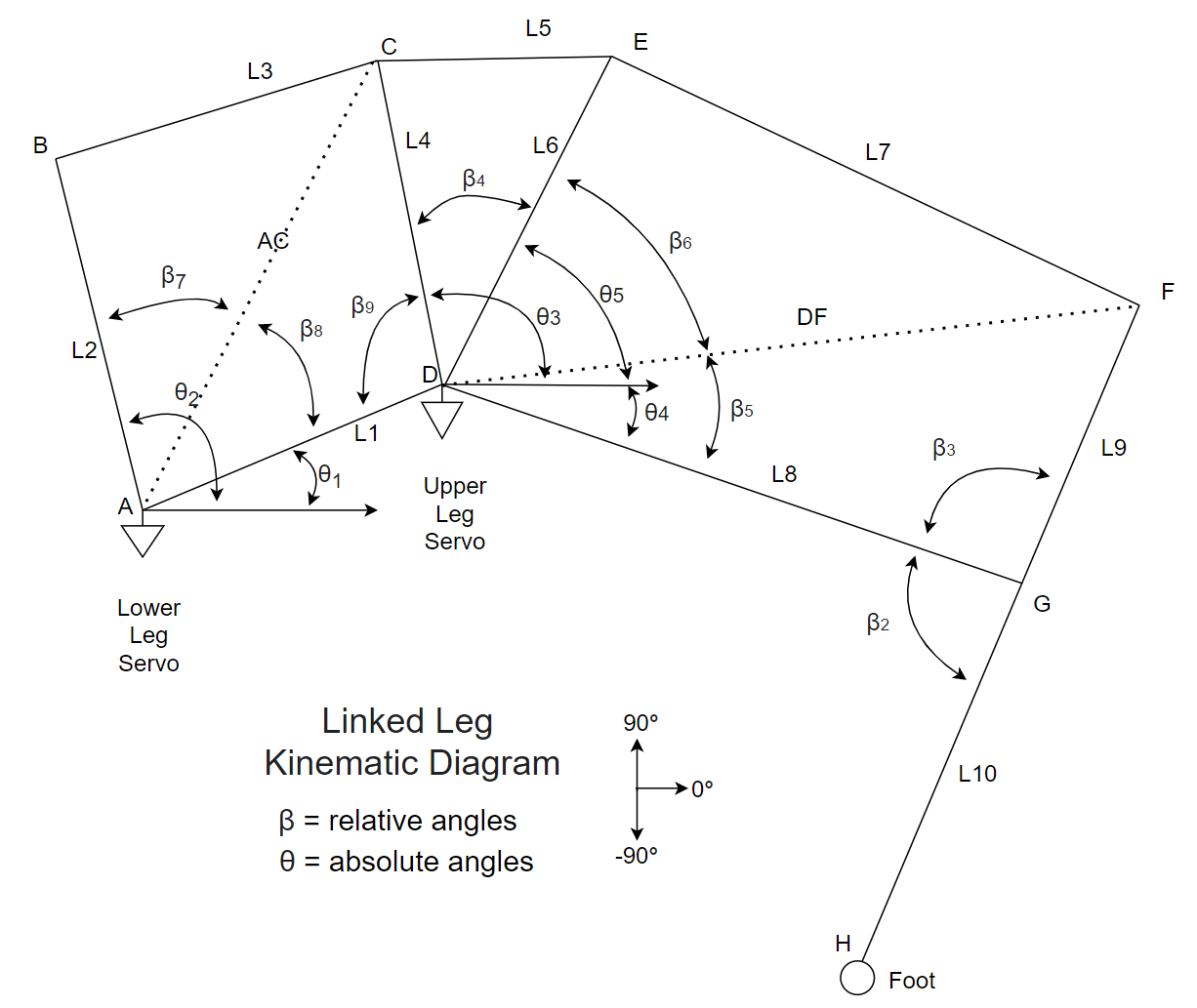
The kinematics diagram of the linked leg locomotion system is the foundation of creating the kinematics calculations. With the positions of the servos and lengths of the segments known, using basic trigonometry the inverse kinematics can be resolved. Meaning, knowing where you want the foot to be located in terms of X Y coordinates the required angles of the two steppers can be calculated.
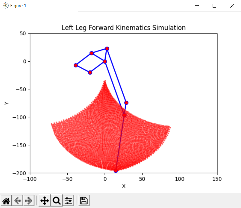
Using matplotlib the forward and inverse kinematics calculations were visually validated.
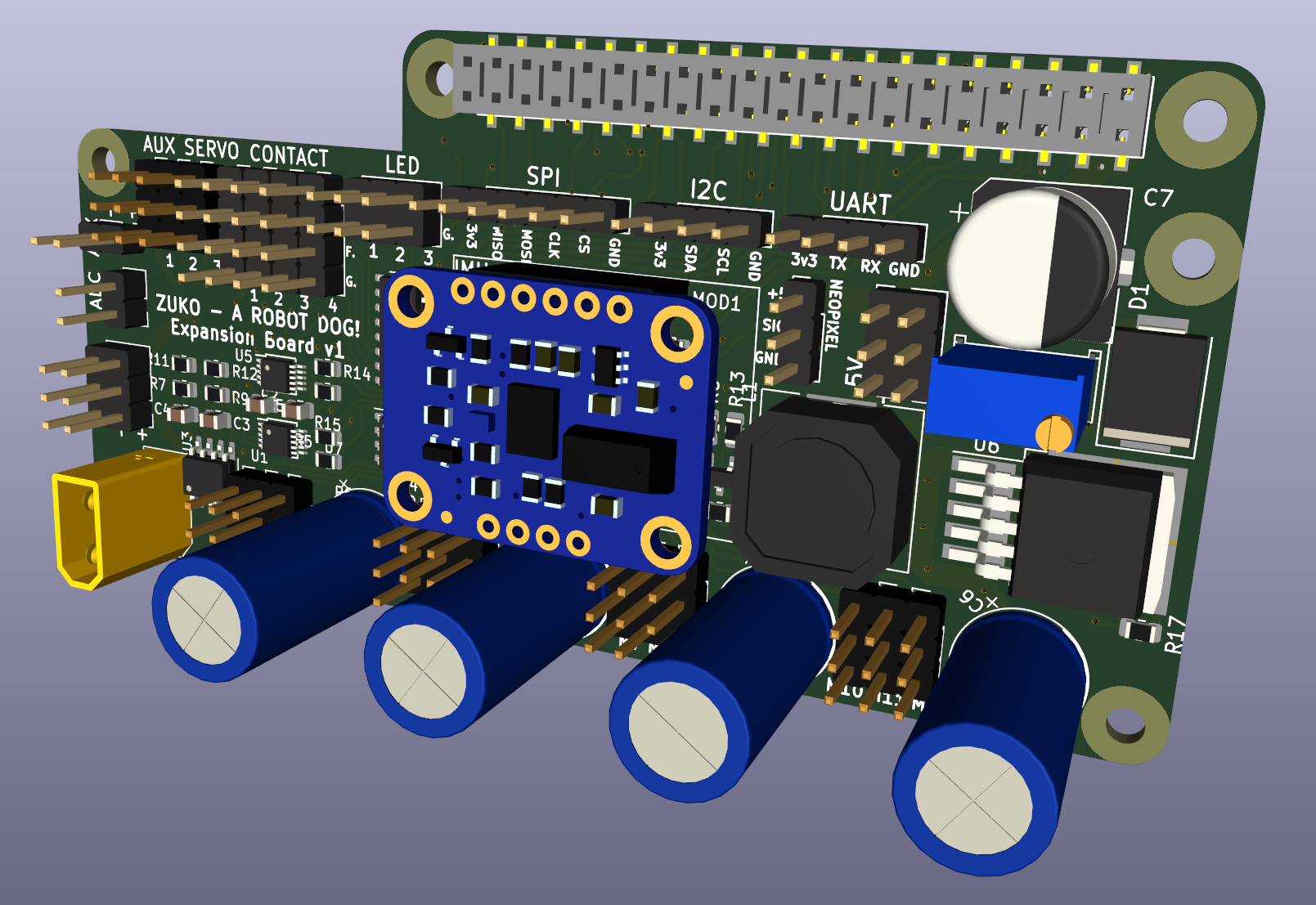
A custom expansion board was created using KiCad that connected directly to the Raspberry Pi's header which was used for driving the 12 RC servos and provided ADC/GPIOs for future functionality. A future version would use a Raspberry Pi Compute Module; a normal Pi was used due to shortages during the Covid 19 pandemic.
The control software uses ROS 2 which at the time was a relatively new release and not as adopted. Therefore, some challenges were faced such as updating the PS4 controller driver and general lack of community discussion.
The link at the end of this post contains all the kinematics simulation code, ROS 2 modules source code, PCBs design files, assembly pictures, and more.
Here is Syndey and Zuko meeting each other for the first time.
Being an incomplete project I don't have much more pictures to show, hopefully I will swing back to this project in the future. I've been dreaming of using BLDC motors with integrated planetary gear reduction like the MIT Cheetah, but smaller actuators like the MG4005-i10.