RGBY-ROM

RGBY-ROM is a special purpose computer using ROM memory encoded as red, green, blue, and yellow acrylic squares.
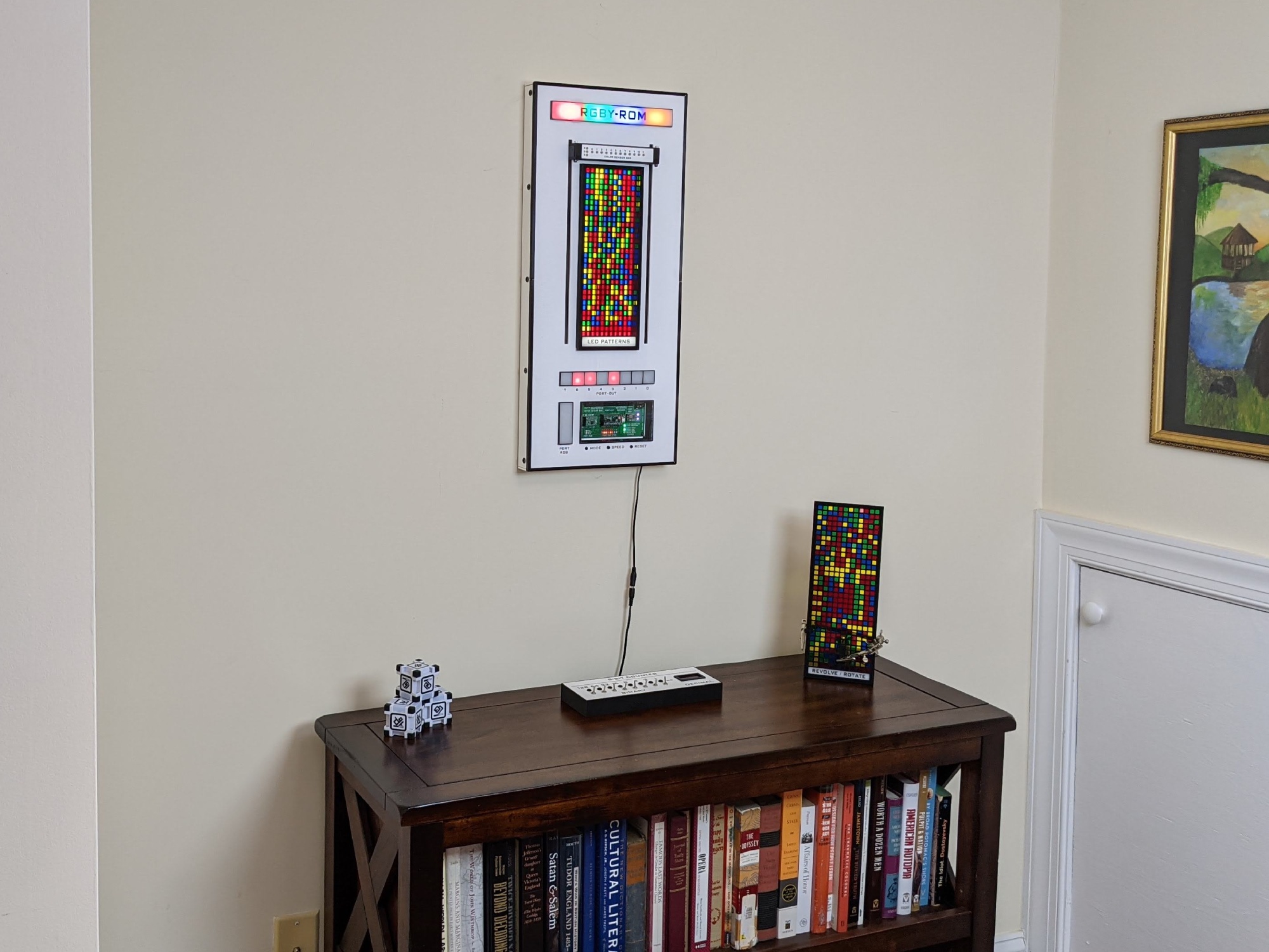
Video of the computer loading a program into memory from the RGBY data cartridge that creates patterns on the LED port.
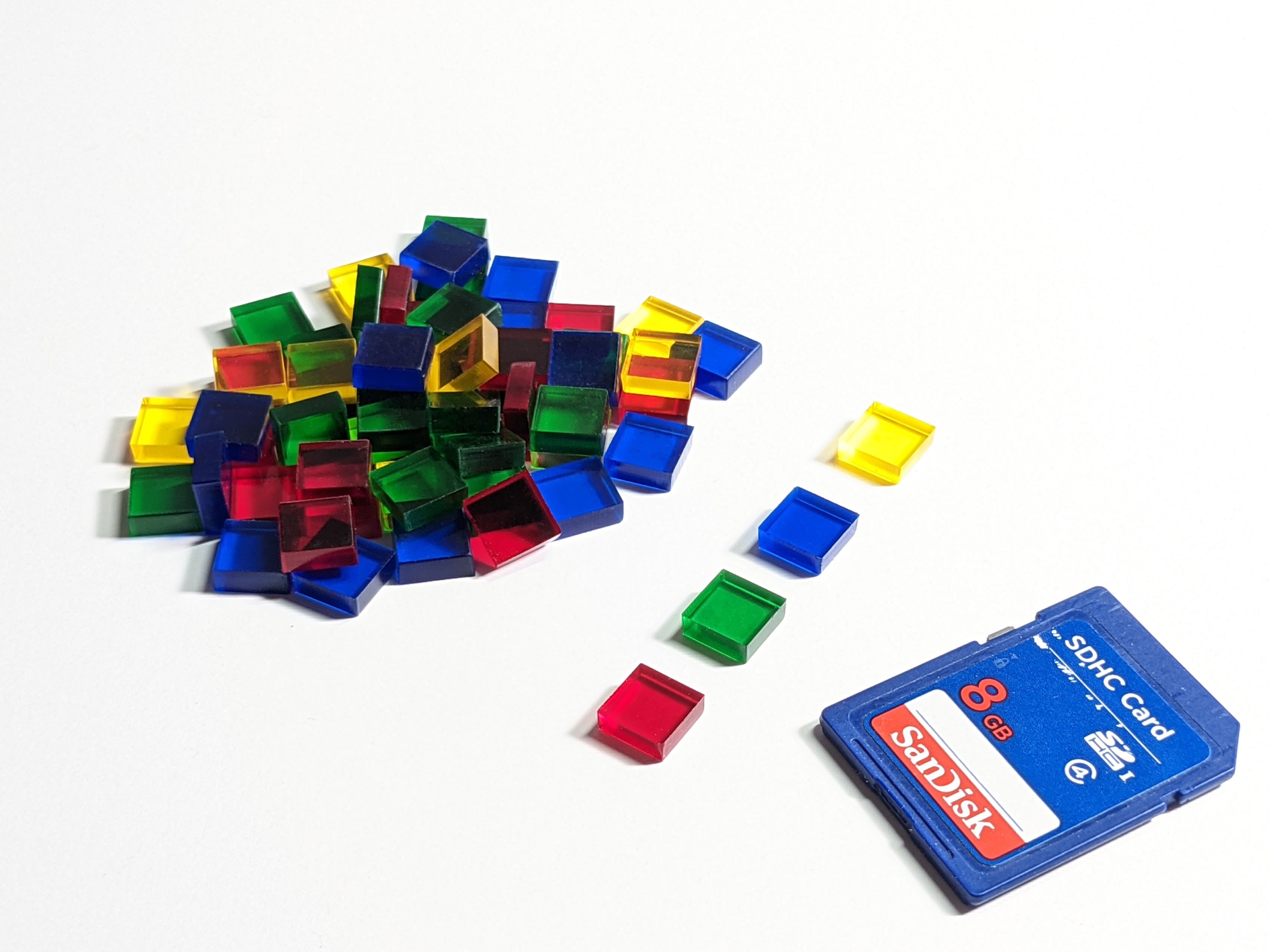
Each acrylic square is called a 'nit' which a coined term that combines bit and nibble creating a representation of data that contains two bits. Four nits are required to make a byte.
| Color | Binary Representation |
|---|---|
| Red | 00 |
| Green | 01 |
| Blue | 10 |
| Yellow | 11 |
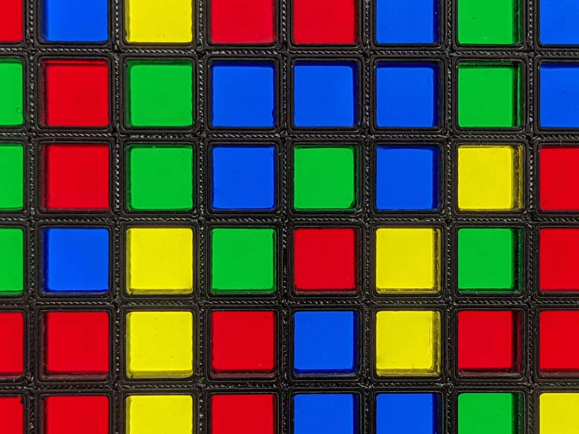
The cartridge is a 3D printed grid.
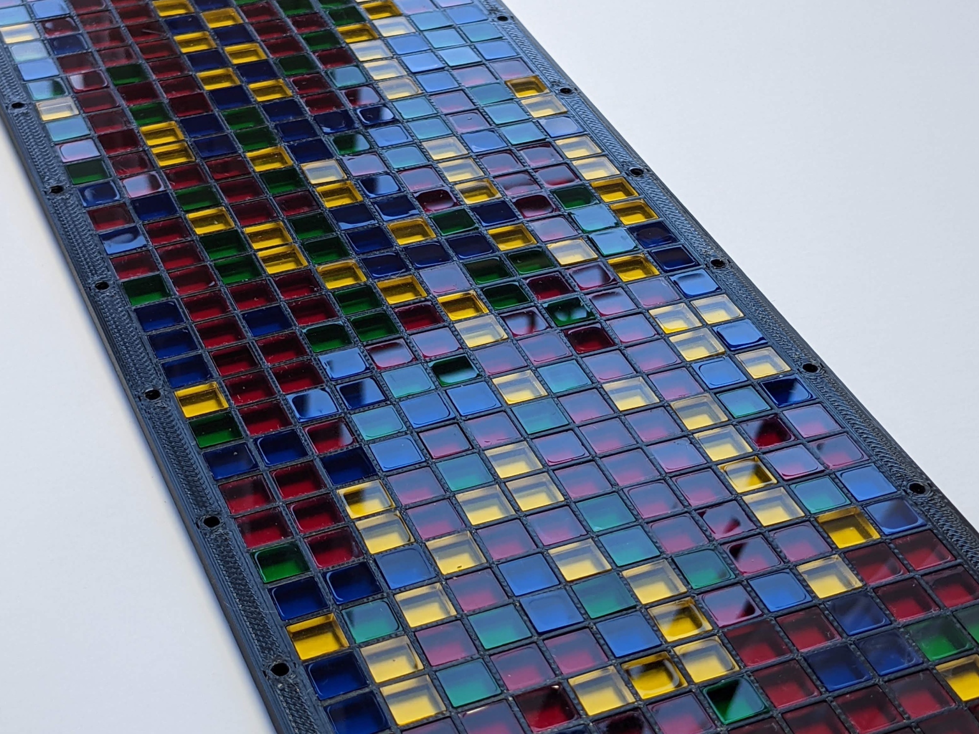
The cartrigde dimensions are 12 nits x 32 nits for a total of 384 nits. 384 nits creates 96 bytes. ASM instructions require 3 bytes per instruction therefore each cartrigde contains 32 instructions.
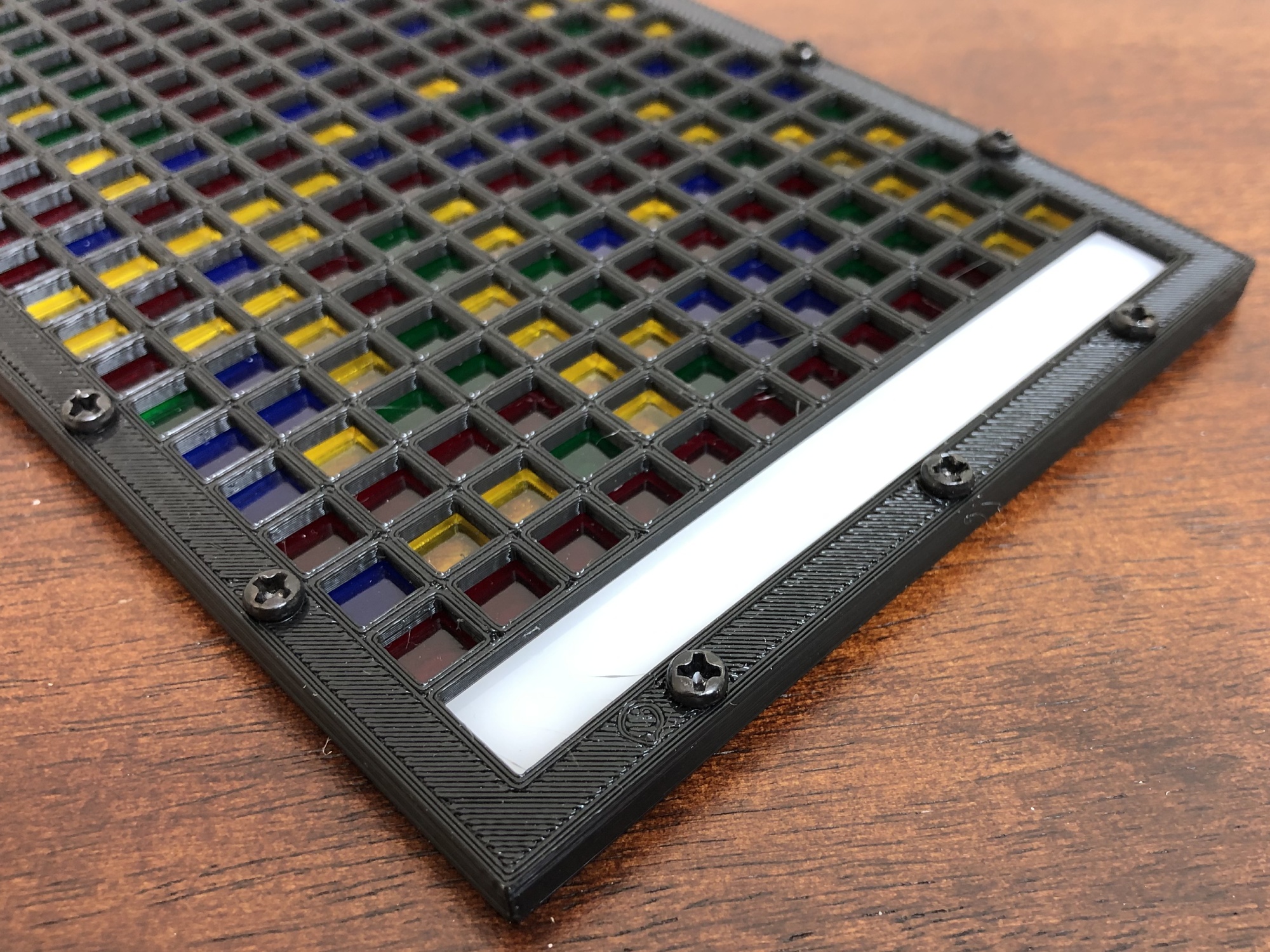
Two halves of the cartridge are combined using screws.
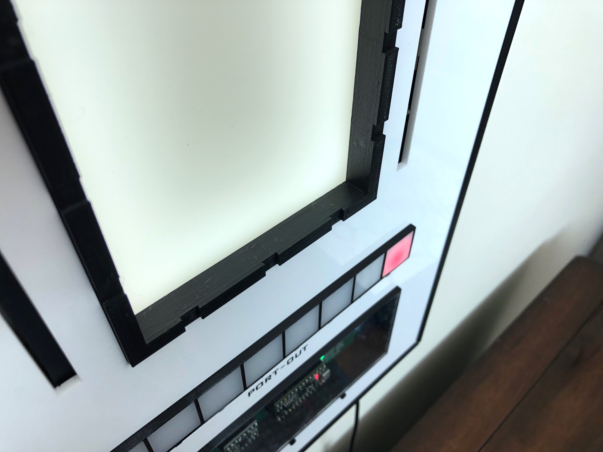
The mounting frame contains embedded neodymium magnets that interact with the screws to hold the cartridge firmly in place.
A video of swaping cartridges.
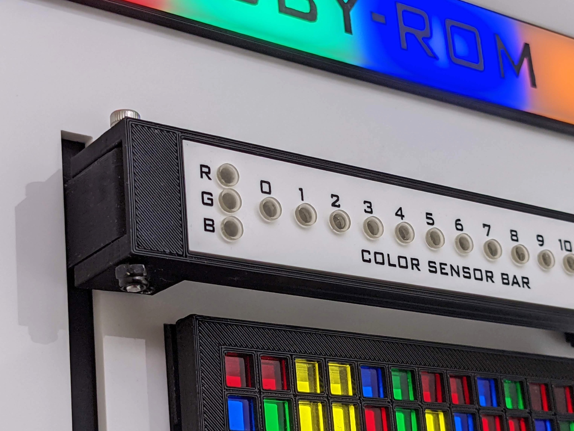
The color sensor bar detects the color of each nit.
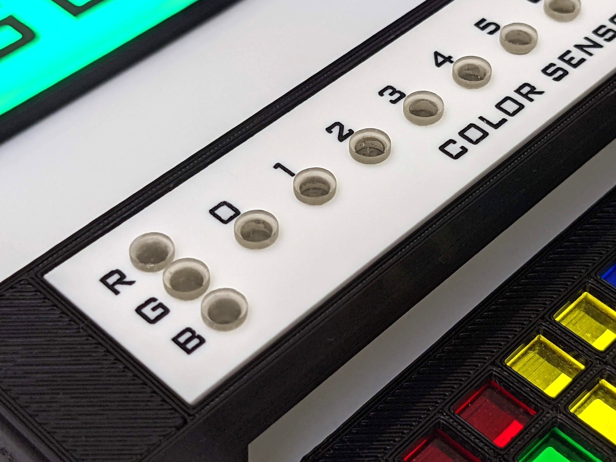
The clear circles are custom light pipes created using an SLA printer that indicates the color of the nit and the index of the nit being processed.
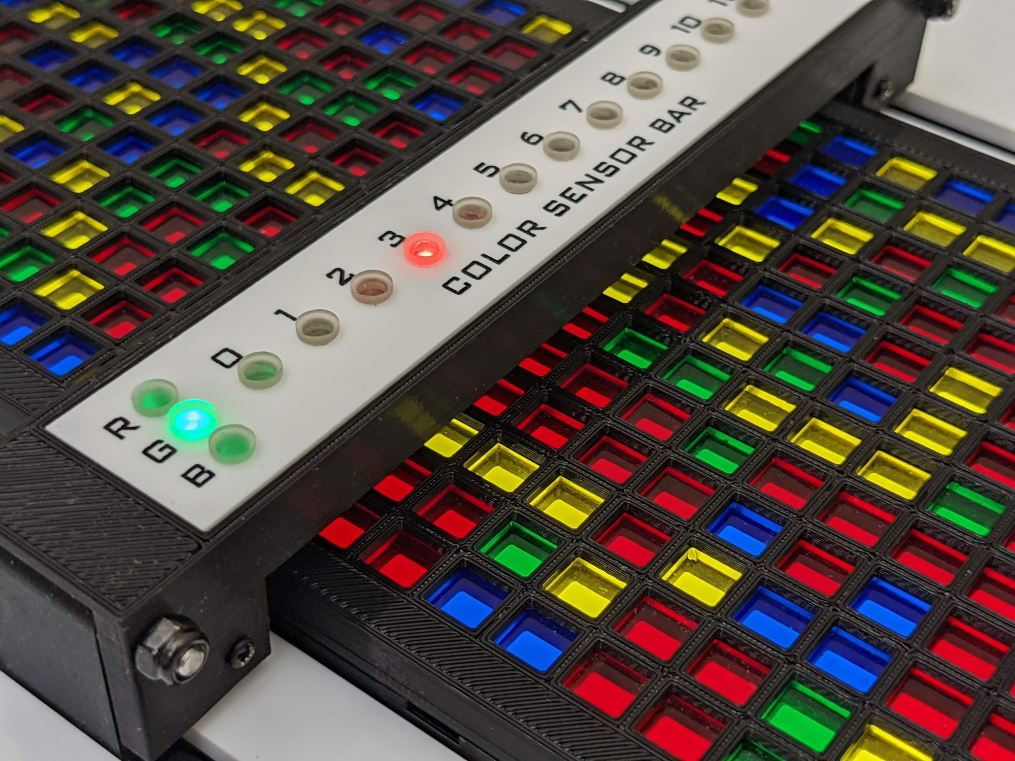
The color sensor bar stops over each row and determines the color of the nit one column at a time. In this picture, the index of the nit is 3 and the nit's color is green.
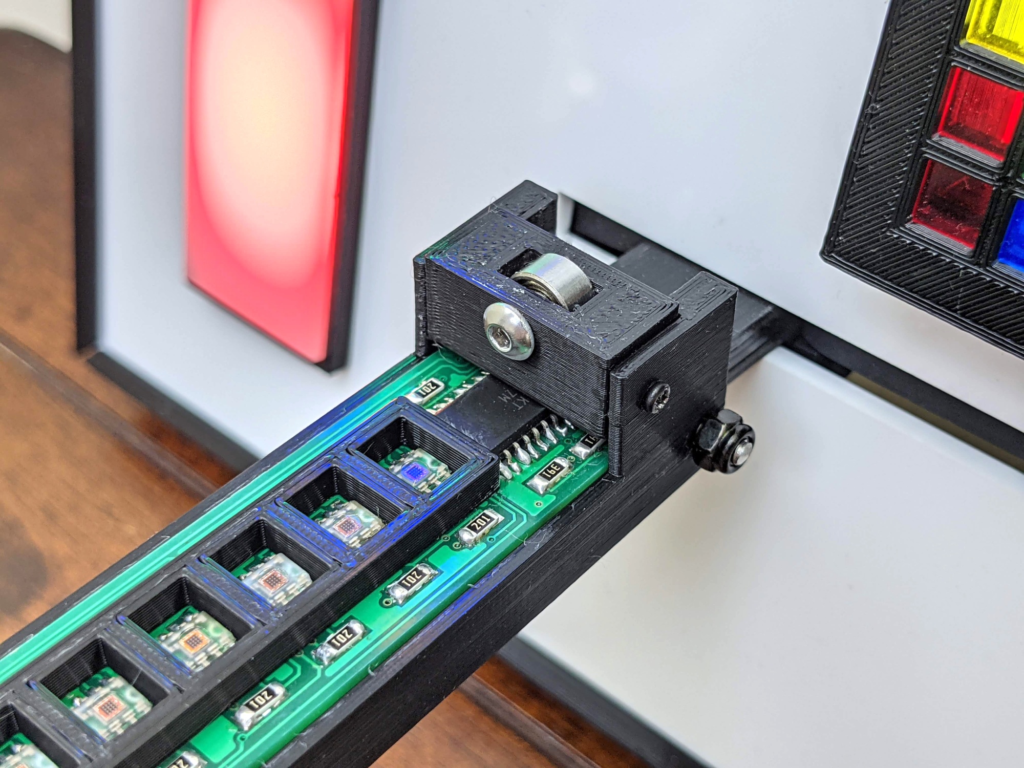
The color sensor bar can unlatch from one side and swivel out. Roller bearings were added to keep the color sensor bar a stable distance from the cartidge to increase color detection accuracy. The color sensors are TCS3200's that convert red, green, and blue colors to frequencies.
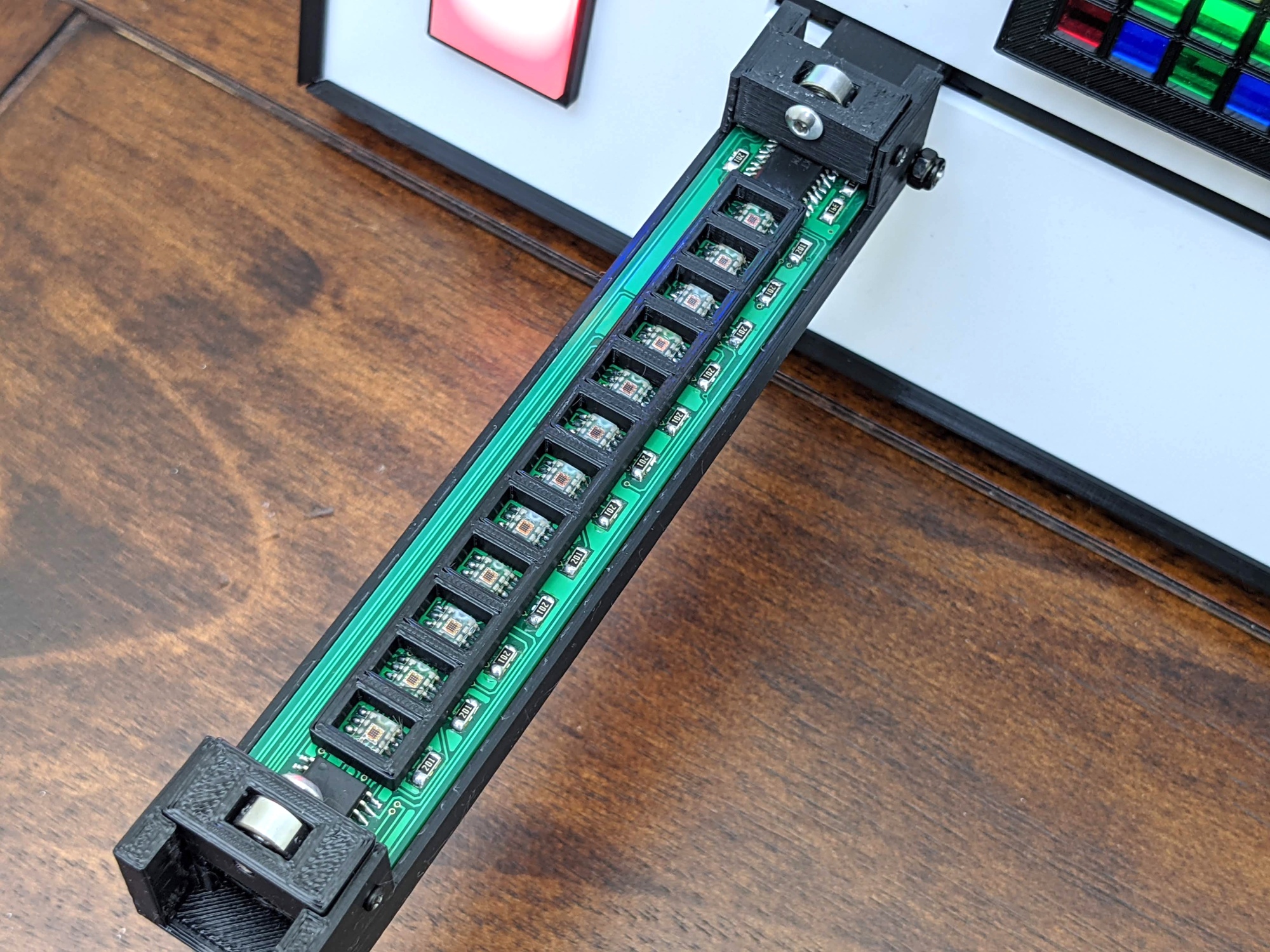
There are twelve TCS3200 sensors, one for each row of the cartrige. The original design attempted using only one sensor on a XY gantry but the mechanics required became to bulky to keep the overall design simple and sleek.
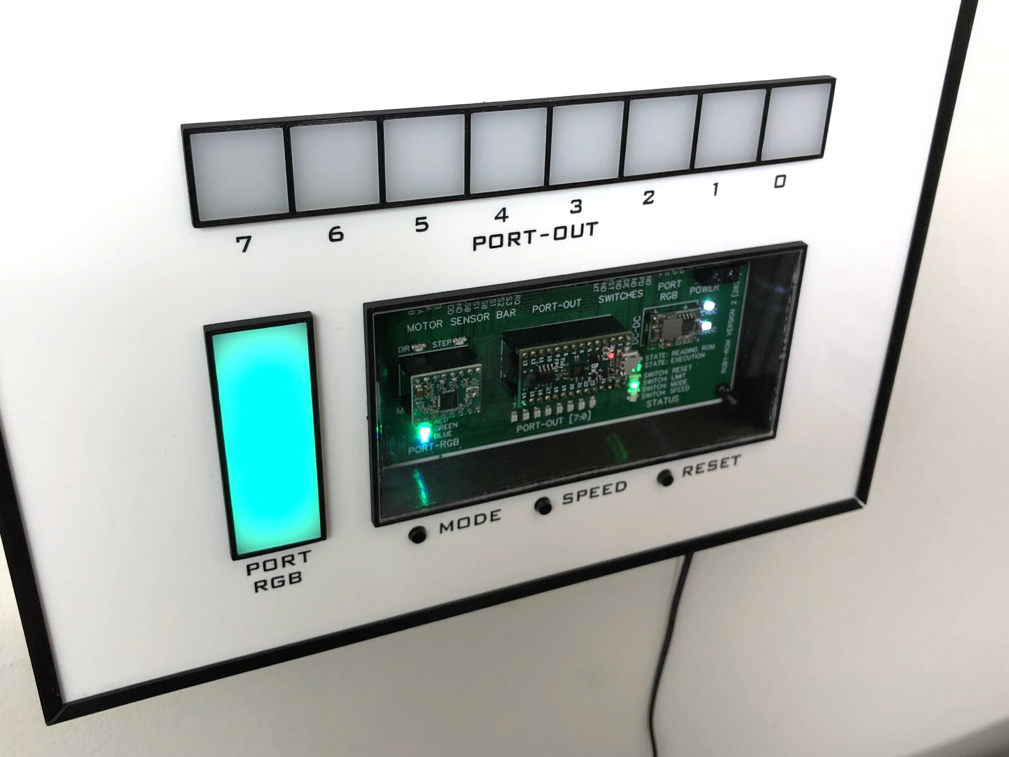
The computer has two output ports: an RGB LED, and a 8 position LED array. There are three buttons: mode, speed, and reset. Mode and speed are accessible to the computer's program and reset is used to reset the CPU and reload the ROM.
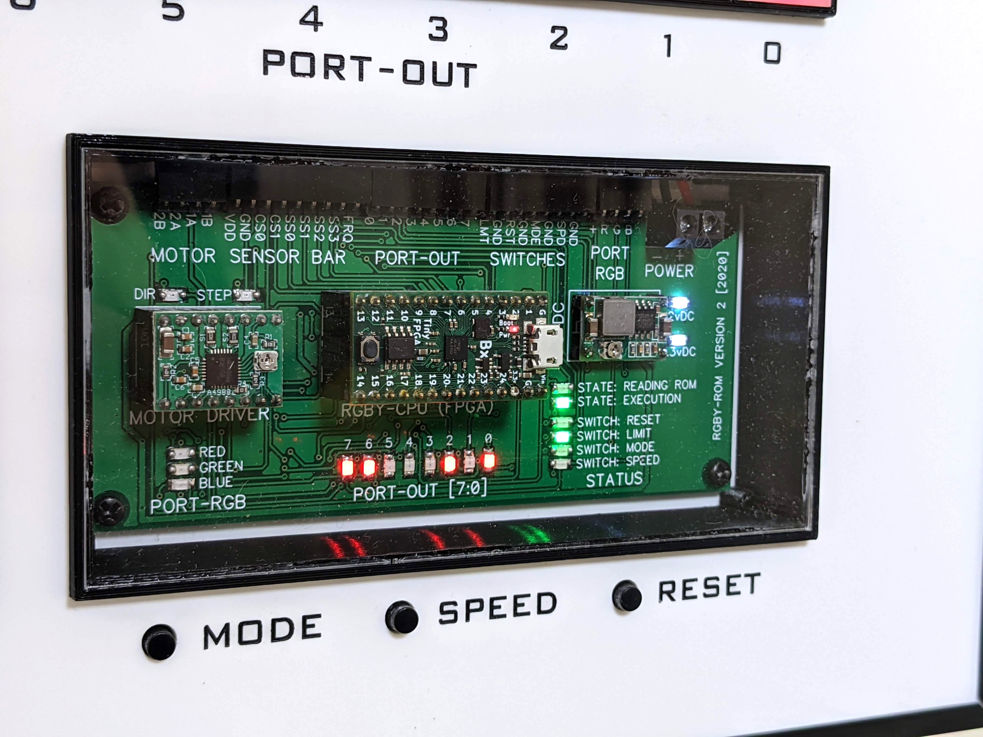
The CPU is instantiated on a TinyFPGA BX FPGA module that uses a Lattice ICE40LP8K. Development was straight forward using the Atom editor with the APIO-IDE plugin.
The main PCB is rather simple and connects a DC-DC power supply, the TinyFPGA, a stepper driver, and breaks outs the various ports.
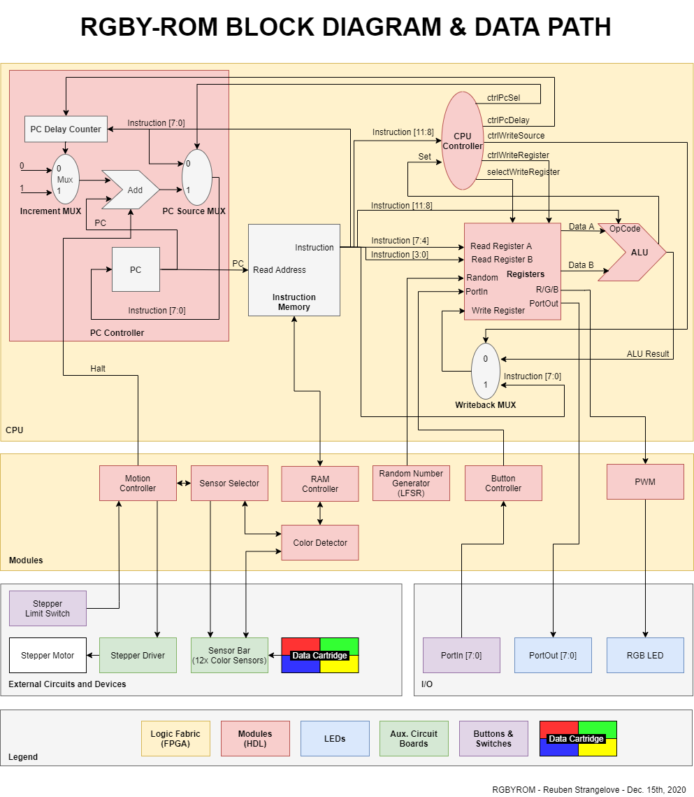
The custom CPU's block diagram shows how the CPU interacts with various modules and external devices. Because the CPU acts as a color controller for RGB lighting and due to the limited instructions, the PC controller has extra logic that delays instructions to assist in creating color and port patterns.
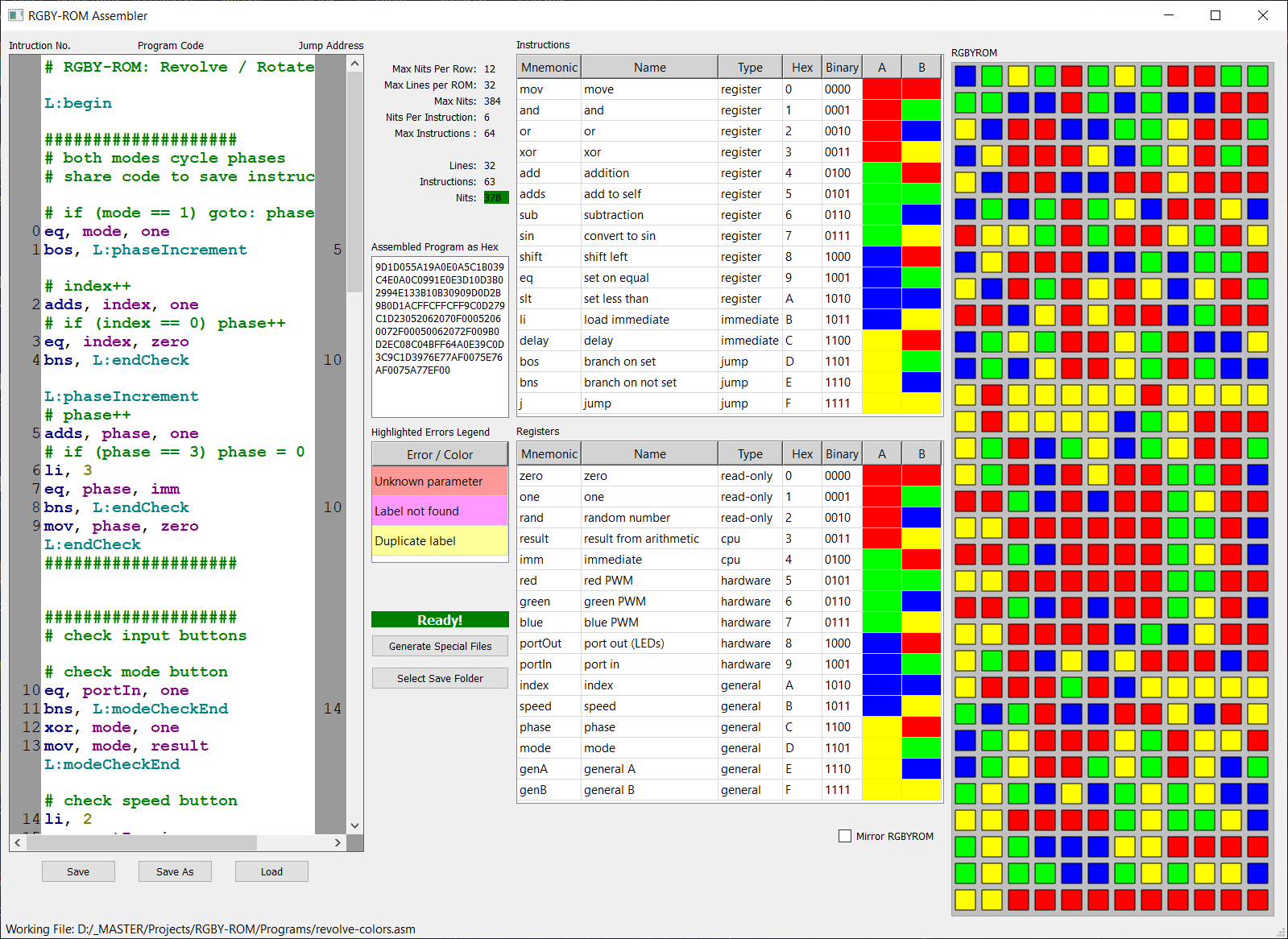
An assembly language and assembler was created from the ground up. The RGBY-ROM Assembly (programmed in QT) is a text editor that displays the available instructions and registers, and updates the resulting color encoded ROM live! The text editor highlights errors in the code such as invalid instructions or too long of a program.
There are three types of instructions: register, immediate, and jump.
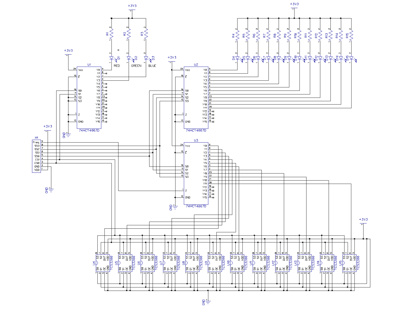
The color sensor bar schematic shows a straight forward design where the LEDs and color sensors are multiplexed to reduce the amount of control lines from the color sensor bar to the FPGA.
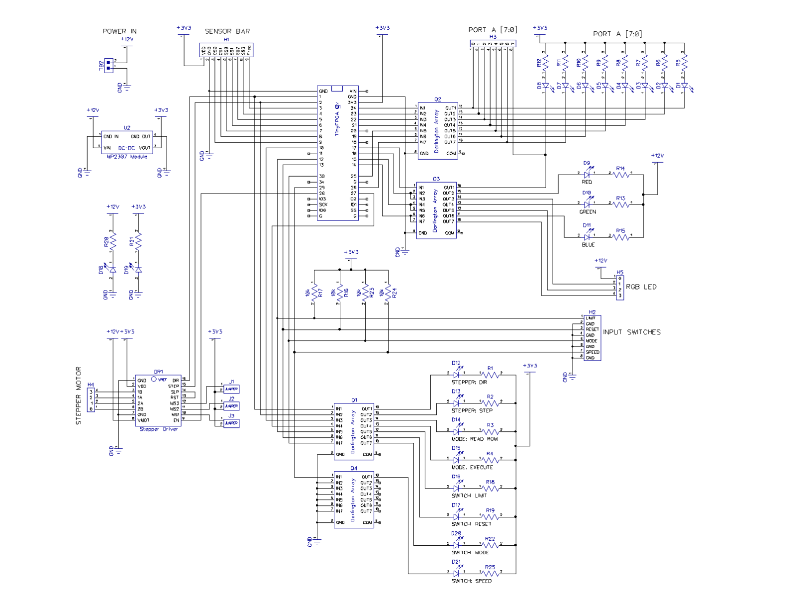
The main board schematic shows the simple nature of the system were the FPGA is the only computational module. The schematics and PCBs were design using DipTrace, but now that KiCad is matured newer projects use KiCad. (but DipTrace is still a very good platform)
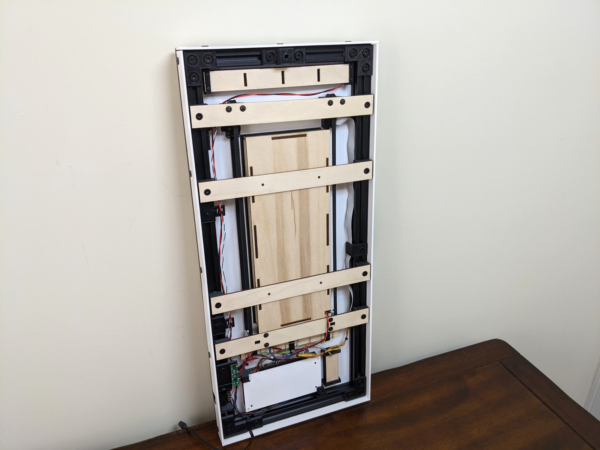
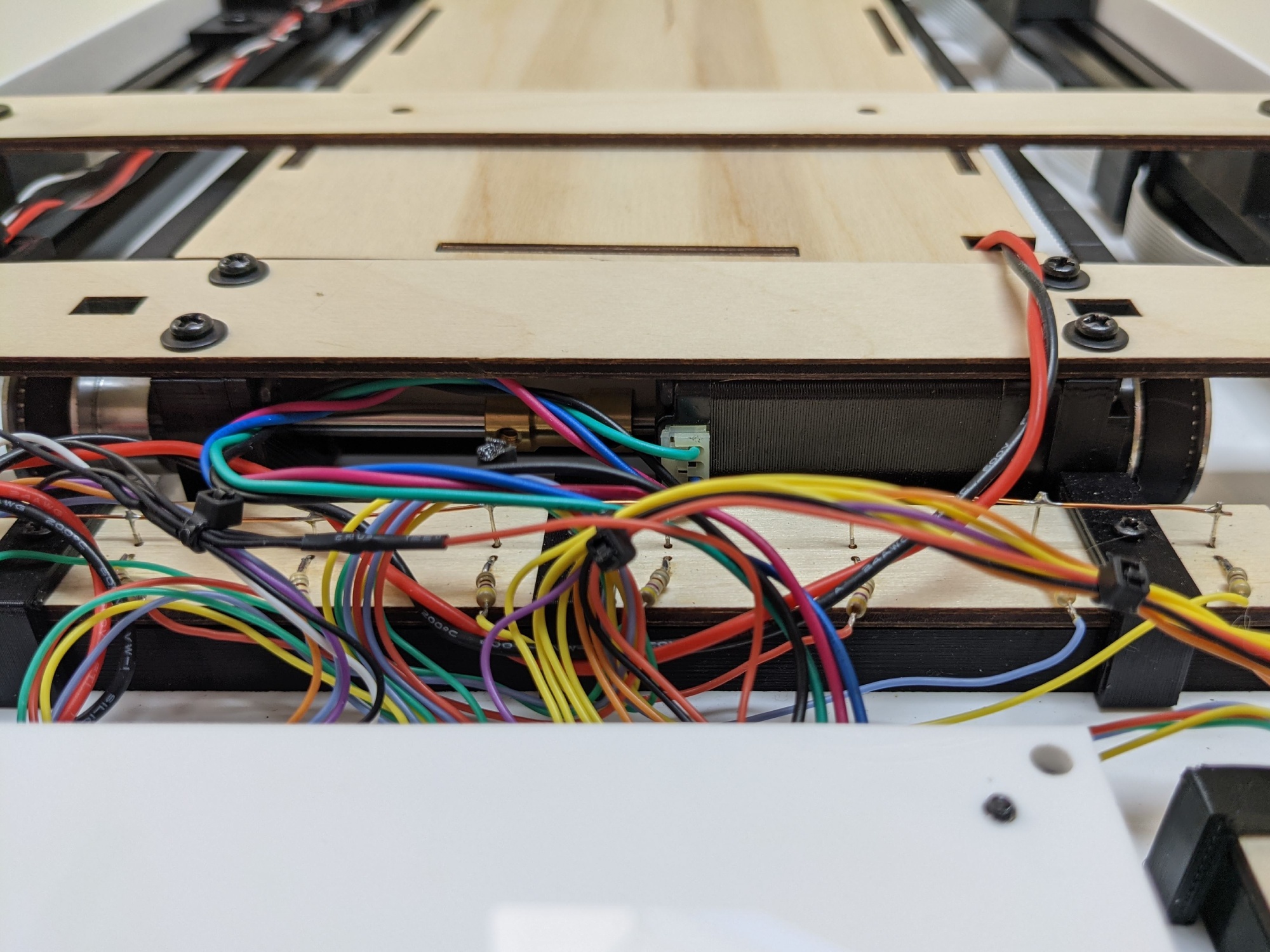
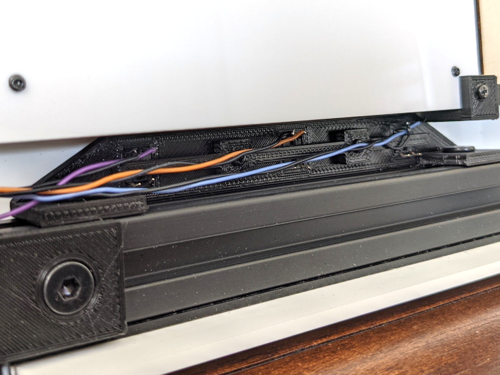
The back of RGBY-ROM reveals the wiring and mechatronics. The frame is made from 2020 aluminum extrusions that creates a rigid frame with mounting points along the perimeter.
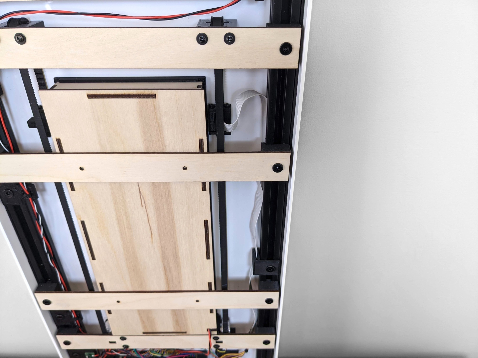
The ribbon cable of the color sensor bar is found the right. The color sensor bar is connected to a belt system.
The main electronics bay is both a bit dirty and clean.
Looking from the bottom up you can see the dual shaft NEMA 14 stepper with pulleys on both sides.
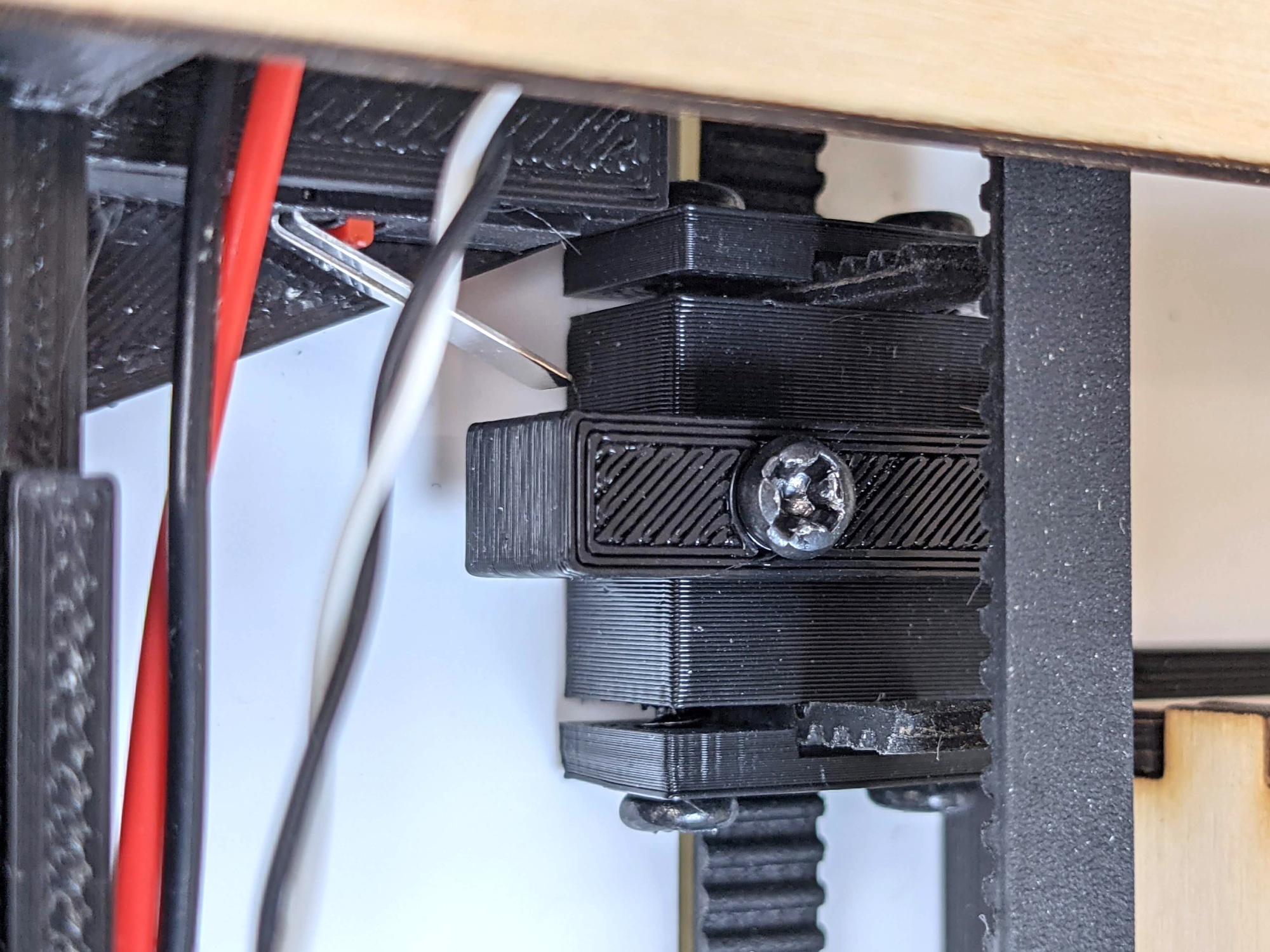
Here is the limit switch for the color sensor bar. All the 3D printed parts were printed using eSun black PLA filament using my QIDI x2 printer (which since has been replaced with Vorons).
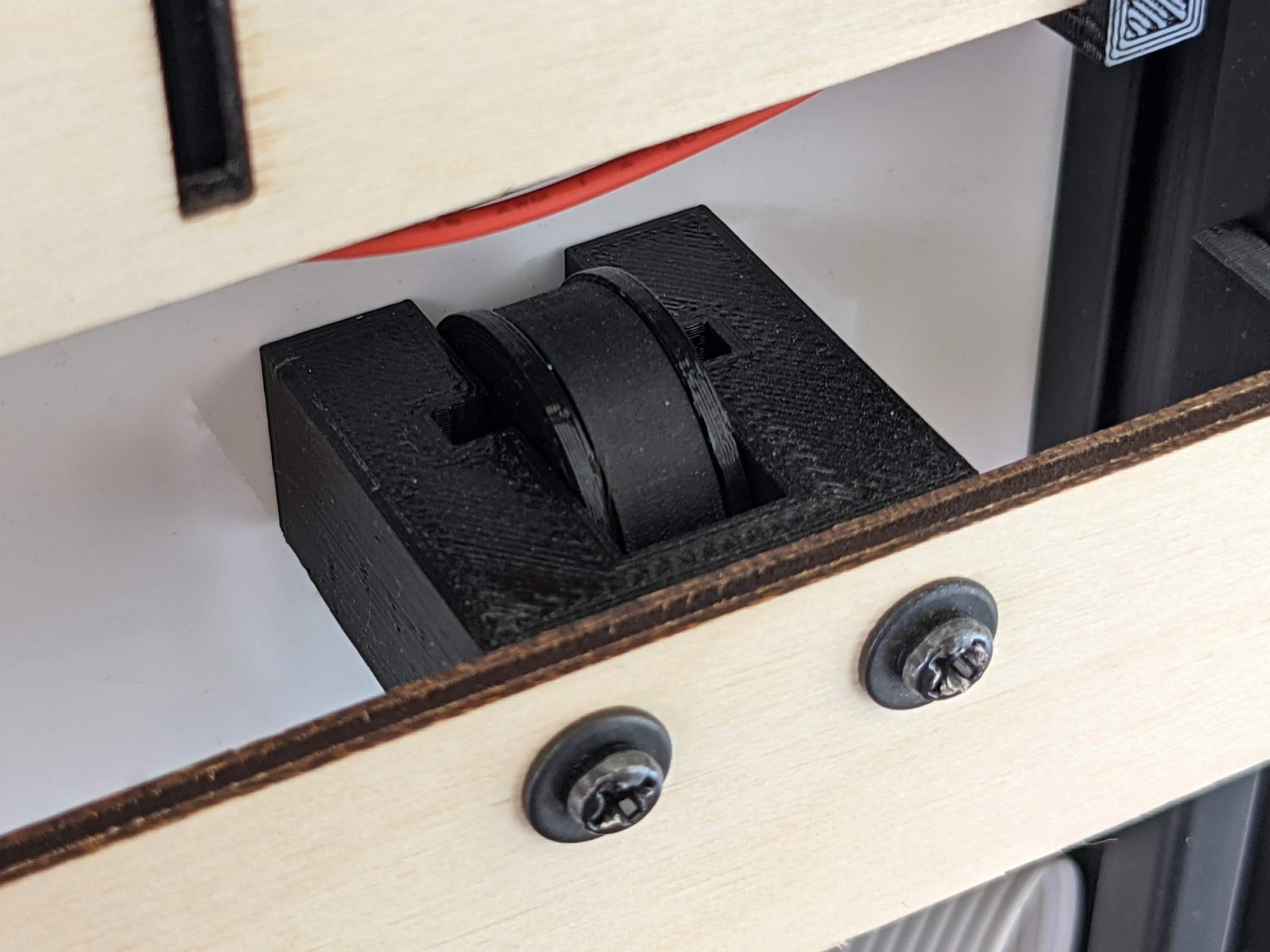
The idles are custom made by combining a printed idler body with small bearings and a 3mm diameter shaft.
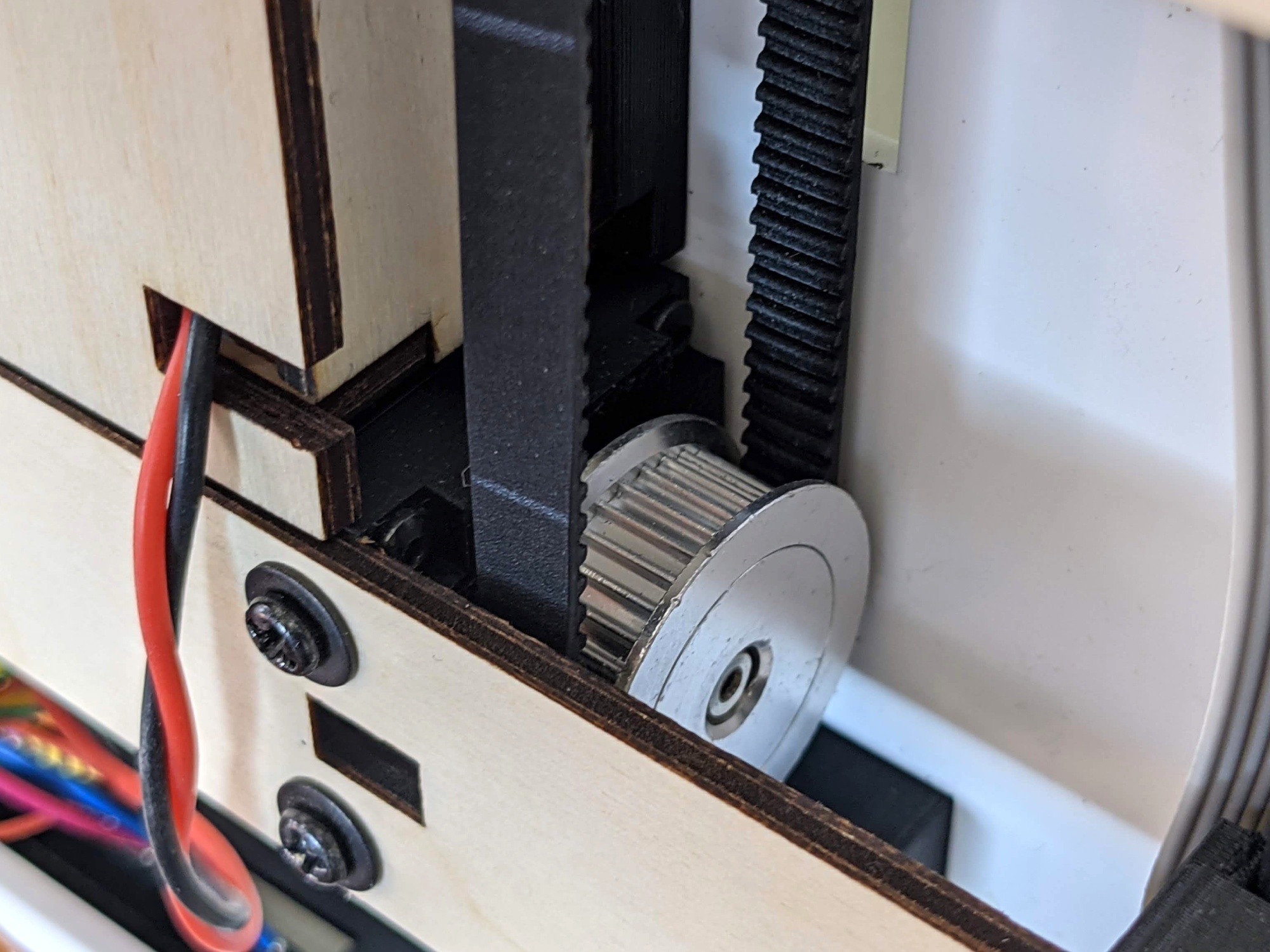
Here is the pulley.
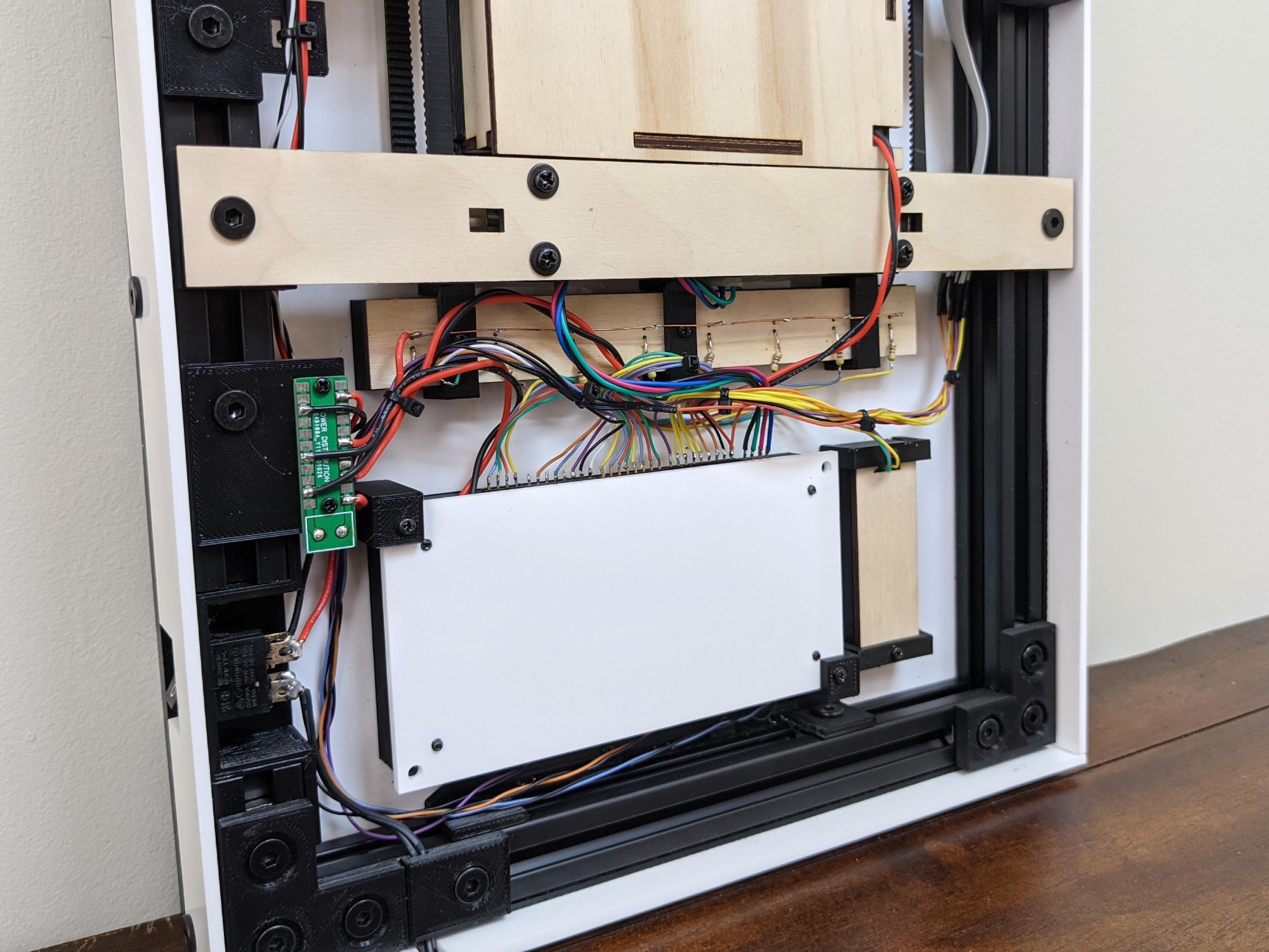
This bracket contains tactile switches for the user buttons.
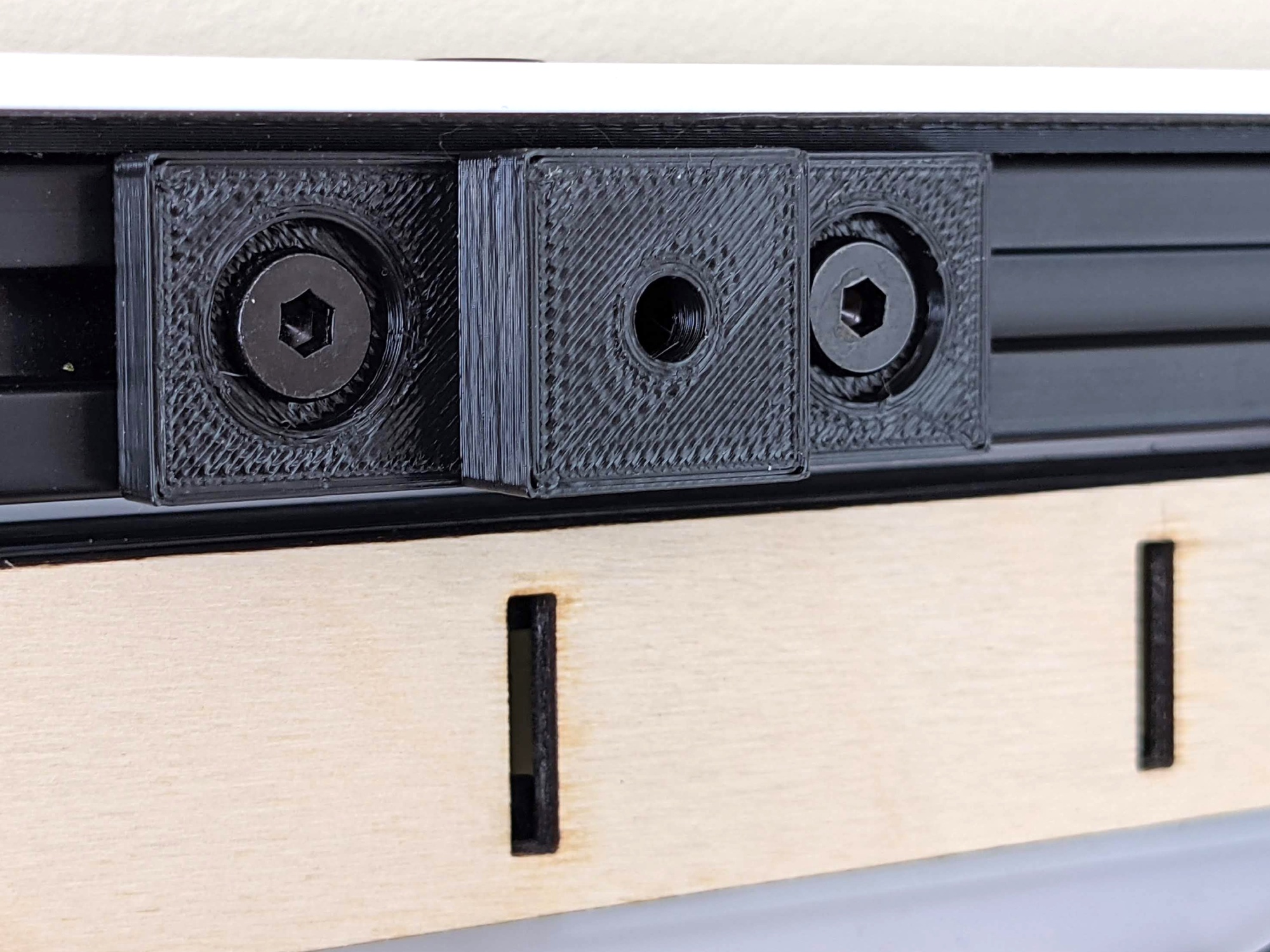
At the top of the frame is the wall mounting plate that couples with a nail.
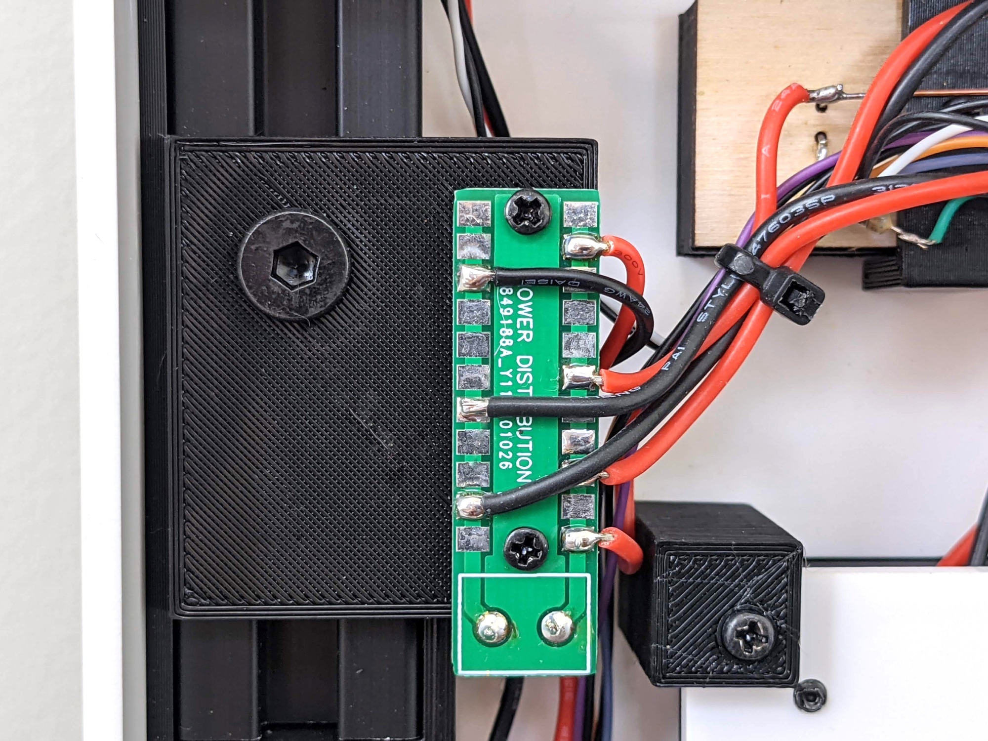
The power distribution hub uses a custom board made for projects like this one.
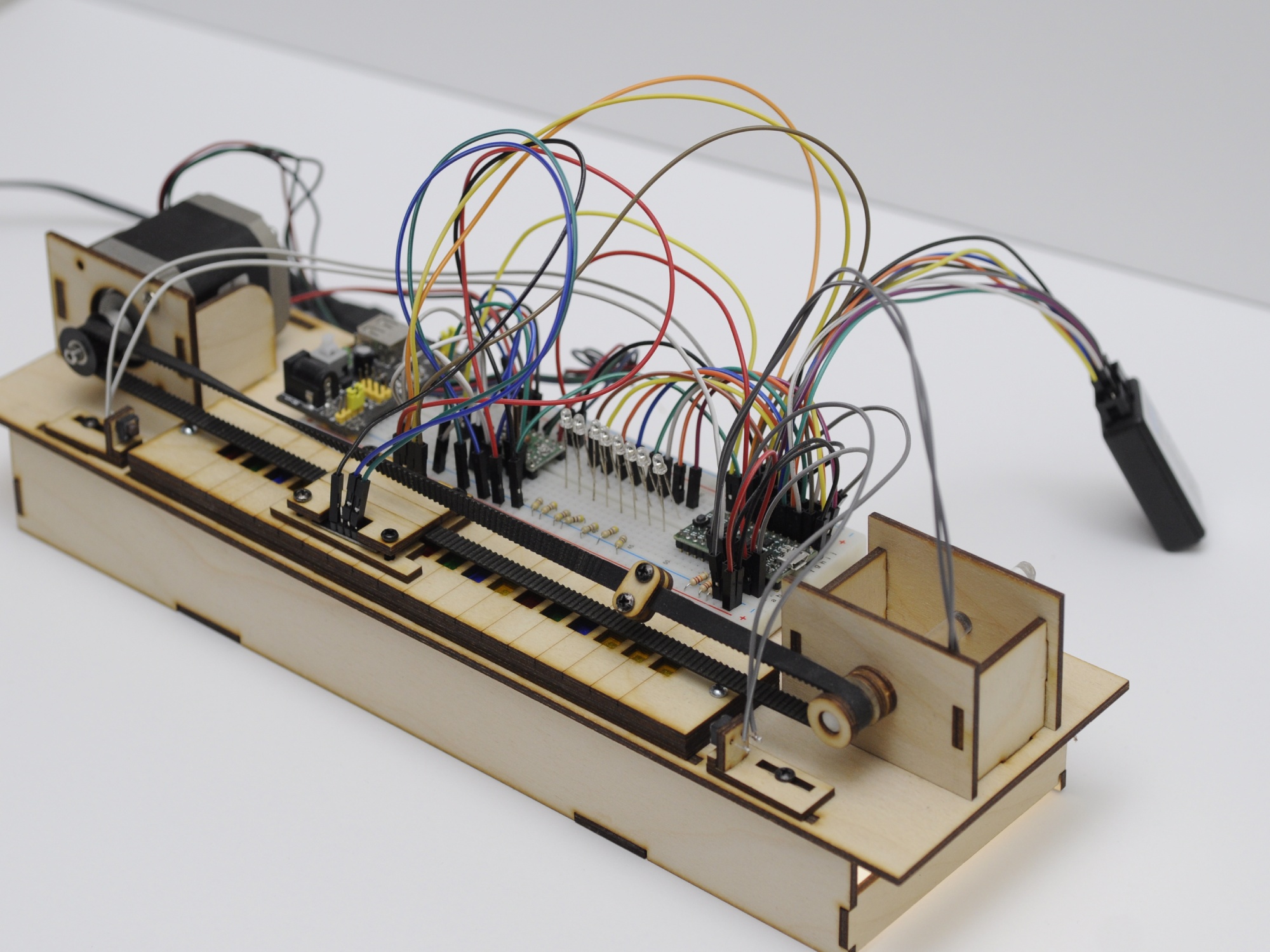
Here is the development platform showing the original intent of using only one color sensor.
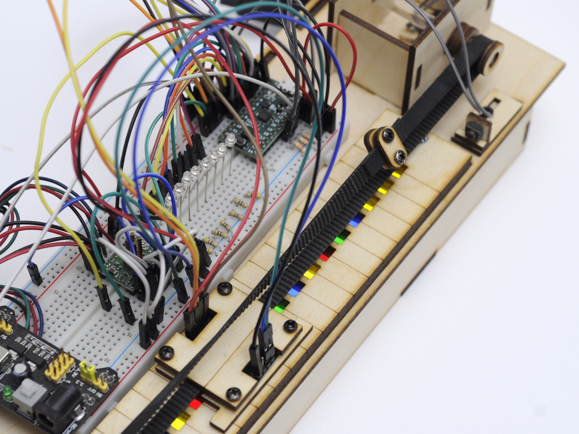
Most of the development was performed on this setup... needless to say a digital logic analyizer along with Sigrok was extensively used.
Glad to you see you make it this far! The RGBY-ROM is in my top favorite projects because it touches so many fun topics: computer engineer, programming, PCB design, mechanical design, 3D printing, and electronic assembly.